Capnscoobing wrote: Mon Oct 06, 2025 7:54 pm

The order is 4-3-2-1, with me testing 2 as ground and 1 as VPWR right?
I'm a little confused with all of this. I was using metal inside the steering column as ground and it was showing the 12v. But... I got curious. With the multimeter and leaving ground in the plug and touching red lead to steering column it shows 12v. When using ground and red lead with pin 4 it shows 12v. I'm not experienced with the multimeter and electrical work so I don't know if this actually means something?
There is a grounded bolt under the steering column but when I go pin 1 and ground to that bolt it doesn't complete the circuit and remains OL. I need to pick up longer wire to try to ground to passenger side (thought I had some but don't).
Meter Set in DC Volts, 20 volt or higher range. Red lead on the No. 1 pin, Black lead on any good ground(Ground or Negative connection is Common to the frame and body and to Battery Negative connection), Ignition in run, should show Battery or Vpower voltage (12.5 volts fully charged battery)! Means no problem with Battery voltage to the Transceiver!
Meter In DC Volts, ignition in run, Red Lead on Pin 1 Black lead on Pin 2 should show the same reading! If it does not show Vpower voltage you have found the problem as that would mean the Transceiver is not getting powered(No ground or Negative connection)!
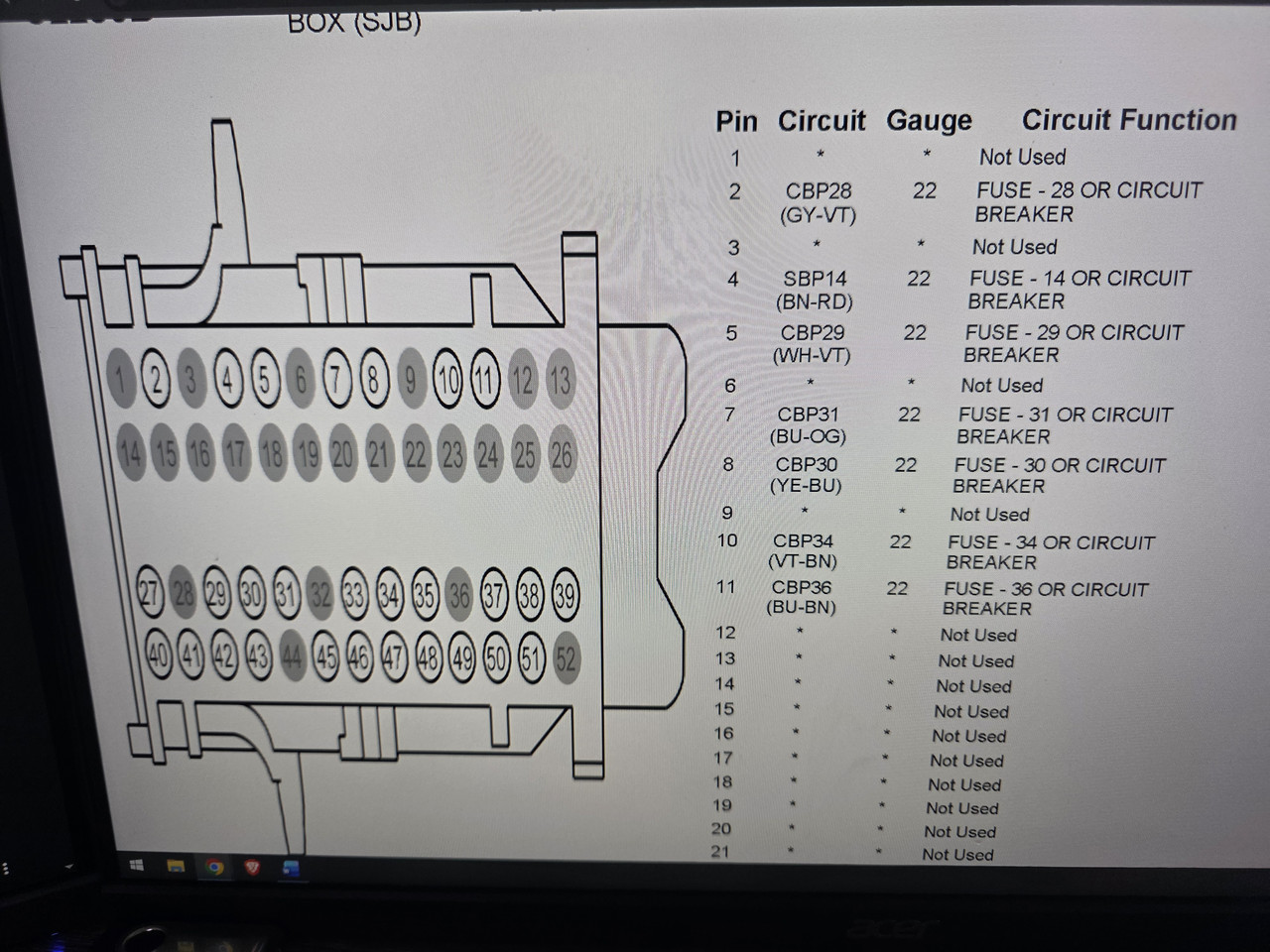
Meter in DC Volts, Red lead on pin 2 and black lead on any good ground(Should not need to connect to ground G201 Behind Glove box (Joh Connector image above and my connector face image in the Mustang wiring diagram Manual show it as circuit G116 The wiring Diagram shows the ground point as G201 in Fire wall behind the Glove box) , Key on and Key off, should show 0 volts or OL, If it shows any voltage, either key position, pin 2 is shorted to Vpower or Vbattery(Possible since you have reported blowing fuse 36 and an inspection of main harness for damage along dash and to Instrument cluster will be required)!
Do not do the next test if the above test shows any voltage! Meter can be damaged. Inspect for harness Damage and repair the shorted circuit first!
Meter in Continuity mode(Diode symbol depending on meter) or lowest Resistance setting, Key in Off. Red lead on pin 2 and black lead on any good ground should show zero Resistance or less than five ohms!
If not then again this is the PATS problem! Negative or ground circuit will need to be repaired!
If problems are found from above and repaired and the keys will now program the following would not need to be performed!
Pins 3 and 4 are Transponder Send and Receive(Violet Grey and Yellow Orange wire respectively) and there is no voltage check for them!
To check them for continuity, Shorts to Ground or To Battery or Vpower, involves disconnecting the respective connector at the Instrument cluster (Connector C220) finding the Transceiver pins at the cluster connector (Pins 22 and 23) and continuity or shorted to voltage or to ground testing the circuit end to end (Transceiver to Instrument cluster)(0 to less then 5 ohms from the pin 3 and 4 to the their corresponding pins 22 and 23 in the Instrument cluster connector (Violet Grey and Yellow Orange wires) and for no connection to ground and no voltage reading while disconnected(no connection to transceiver pin 1 (with Key in run or in Off) Any voltage reading, 0 resistance Continuity reading to ground or OL open circuit End to End!
Hope that helps with the confusion or maybe just makes more confusion?