Flashing Modules - External charger setup

Testing new functions
NvTwist
Posts: 12
Joined: Fri Nov 04, 2022 4:18 am
Vehicle: The only 5yr old ‘17 Raptor that’s still 100% stock

Re: Flashing Modules - External charger setup

Post by NvTwist »

spender2611 wrote: Mon Dec 19, 2022 9:11 am
NvTwist wrote: Fri Dec 16, 2022 1:29 pm
spender2611 wrote: Fri Dec 02, 2022 10:06 am
Does your car show the message that it will shut down because of battery saving?
The primary reason for connecting a charger/PS to the vehicle is to prevent the vehicle from going to sleep shutting down Acc power and turning off the ignition while programing.
You are absolutely correct, but he said that his car also shuts down with a charger connected to the battery. So my qestion was if there is a message on the display or the car is just shutting down.
If the charger is connected directly to both battery terminals (+ & -) the vehicle can and will shut down/Sleep.
To prevent the shut down the chargers - Negitive clamp needs to be connected to the Chassis/Body ground and the positive to the + battery terminal as normal.
spender2611
Posts: 56
Joined: Sun Dec 26, 2021 9:39 am
Vehicle: Ford Focus MK4 1.0 125PS 2019

Re: Flashing Modules - External charger setup

Post by spender2611 »

f
NvTwist wrote: Mon Dec 19, 2022 7:53 pm
spender2611 wrote: Mon Dec 19, 2022 9:11 am
NvTwist wrote: Fri Dec 16, 2022 1:29 pm The primary reason for connecting a charger/PS to the vehicle is to prevent the vehicle from going to sleep shutting down Acc power and turning off the ignition while programing.
You are absolutely correct, but he said that his car also shuts down with a charger connected to the battery. So my qestion was if there is a message on the display or the car is just shutting down.
If the charger is connected directly to both battery terminals (+ & -) the vehicle can and will shut down/Sleep.
To prevent the shut down the chargers - Negitive clamp needs to be connected to the Chassis/Body ground and the positive to the + battery terminal as normal.
So if a normal charger - like the CTEK MX - is connected to the + of the battery and the - to the chassis ground it will not shut down/go to sleep?
Ford Focus MK4 ST-Line 2019 Turnier
NvTwist
Posts: 12
Joined: Fri Nov 04, 2022 4:18 am
Vehicle: The only 5yr old ‘17 Raptor that’s still 100% stock

Re: Flashing Modules - External charger setup

Post by NvTwist »

That’s correct, depending on the vehicles amperage draw it that charger can supply the needed current the vehicle will go woke. :roll:
If the chargers output isn’t enough it can still be used to prevent the sleep event but eventually the battery voltage will drop to low and trigger battery charge preservation and shut down the car.
spender2611
Posts: 56
Joined: Sun Dec 26, 2021 9:39 am
Vehicle: Ford Focus MK4 1.0 125PS 2019

Re: Flashing Modules - External charger setup

Post by spender2611 »

Can you recommend a charger? :) thank you!
Ford Focus MK4 ST-Line 2019 Turnier
NvTwist
Posts: 12
Joined: Fri Nov 04, 2022 4:18 am
Vehicle: The only 5yr old ‘17 Raptor that’s still 100% stock

Re: Flashing Modules - External charger setup

Post by NvTwist »

spender2611 wrote: Wed Dec 21, 2022 9:16 am Can you recommend a charger? :) thank you!
No I can’t recommend one. I will share the charger that I’ve been using to power my f150. It’s model Tower Top TP108MB… I have NO idea if it’ll work as well for you & your vehicle so The risk is yours.
Focus-MK4
Posts: 89
Joined: Sun Sep 23, 2018 1:51 pm
Vehicle: Ford Focus MK4 - EcoBlue 1.5

Re: Flashing Modules - External charger setup

Post by Focus-MK4 »

spender2611 wrote: Tue Dec 20, 2022 10:44 am So if a normal charger - like the CTEK MX - is connected to the + of the battery and the - to the chassis ground it will not shut down/go to sleep?
I have tried different variants but the result is always the same, sync displays that the battery status is low and is shutting down after several minutes. Even after been able to turn off DRL now. So only Modules, IPC and Sync Display are running.

Tried connecting CTEK Charger (5A) to
- battery directly to + and -
- through BMS so battery + and ground on chassis

Haven't checked the time but around 10/15 Minutes the Car shuts down with the message in SYNC. It's possible to turn on again everything but then after around 5 minutes everything shuts down again.
Ford Focus MK4 YouTube Channel http://youtube.de/c/My-Ford-Focus
Ecmbuster
Posts: 2433
Joined: Sun Mar 15, 2015 4:08 am
Vehicle: Subaru, Volvo Bertone and two Motorcycles
Location: On a spinning rock

Re: Flashing Modules - External charger setup

Post by Ecmbuster »

Part 1
I don't know if I should laugh or cry. I can see why "Fake News" is word of the year in 2017 and still is today.
Each and every one of you need to back to school and learn "Ohm's Law and Kirchhoff's Circuit Laws (KCL)"
The next course taken is "How a CAN Network Operates".

One more time:
The posted advice is ..................................
Absolutely incorrect and NOT advisable - PERIOD!
Read the last entry and get educated.
https://forscan.org/forum/viewtopic.php?f=4&t=22115

Been there, done that, wrote books about it, have all the "T" shirts.
Battery chargers are garbage, a floating power supply is the only correct method.

Have any of you even considered testing a parasitic draw just with the ignition turned ON?
My guess is NO!


Try it, it's not difficult and a step forward towards learning some of "Ohm's Law and Kirchhoff's Circuit Laws (KCL)"
Instead of posting this nonsense, get one of these tools and LOOK AT IT!
UNI-T AC_DC.jpg
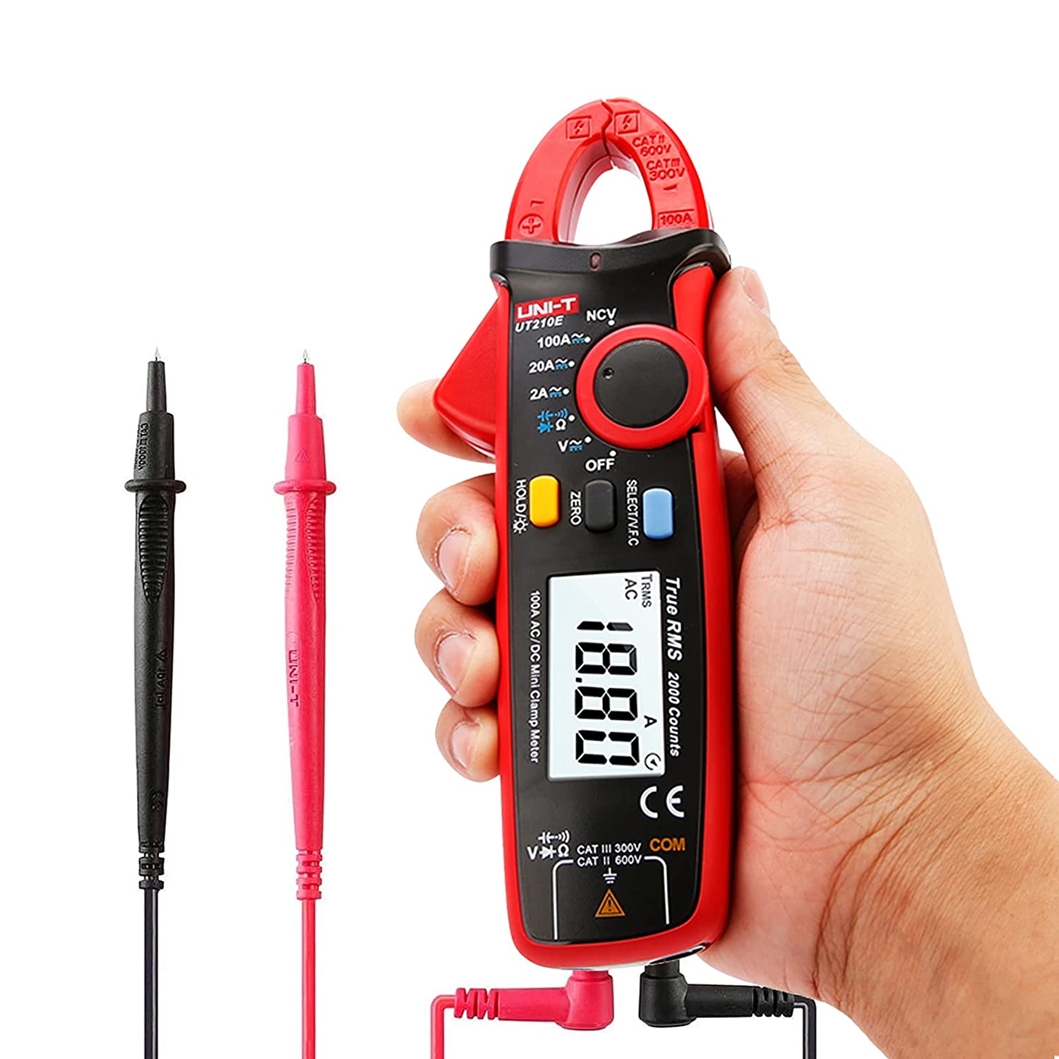
UNI-T AC_DC.jpg (125.97 KiB) Viewed 2356 times
KOEO - Attach the clamp and test the parasite at the negative cable first.
KOEO - Attach an AMP clamp to that mickey mouse POS battery charger, what is the current output?
Answer - Less than the parasitic draw.
One way or another, the system will fail and force it self to sleep. Worst case, "Another Brick In The Wall".
One more time, a POWER SUPPLY is recommended, NOT a battery charger.
The one that I use is a 90 AMP floating power supply and can remain attached all year long with NO damage to the system.

Part 2
The network, how is it kept alive during diagnosis and maintaining electrical stability?
1) A proper and clean output power supply
2) A functioning quality scan tool - active within the network.
3a) Network wake up - added electrical loads such as 4-Way Emergency Flashers.
3b) This simple test will keep a network active providing number 1) is correct.
4) When stable, all electrical consumers should be turned off according to any flash or update instructions.
5) The truth holds during a diagnostic session, unwanted consumers should be in the OFF position.

Without the driver intervention, some networks will "wake up" from time to time to "self check" and perform maintenance.

There are also common instances when the network will NOT enter sleep more AFTER the key was removed because:
A) the engine is HOT
B) the PCM and fuel pump remain ON
C) the fuel pressure / temperature and pump is monitored until the potential of a vapor lock is eliminated (cooled).
D) this is common with - GDI or direct injection vehicles.

So imagine, programming a PCM in that condition? - "Another Brick In The Wall".

During any and all diagnostic sessions, programming sessions, voltage and current are closely monitored and never trashed or bricked a controller.

The earth is still round last time it was calculated by the Ancient Greeks.
magatards are an evolutionary mistake - only time and evolution will take care of that mistake.
E = I X R is perfection
Light travels 300,000,000 Meters in one second - still hasn't changed.
The speed of electricity or velocity factor is not the same as the speed of light.
The velocity factor can range between 50% to 95% dependent and on many factors.
Ohms Law Relationship.pdf
(299.44 KiB) Downloaded 181 times
Kirchhoffs Circuit Law.pdf
(206.35 KiB) Downloaded 143 times
Do not ask for help in PM. Use the forum to ask and answer questions! There's a special place for NOT following up!
spender2611
Posts: 56
Joined: Sun Dec 26, 2021 9:39 am
Vehicle: Ford Focus MK4 1.0 125PS 2019

Re: Flashing Modules - External charger setup

Post by spender2611 »

//Offtopic

@Ecmbuster

Give simple and short answers/advices that stupid people like we are will understand it.

Do you feel that you are kind of an elite or something cause you are well educated in physics or electricity?

You maybe shouldnt go back to school but get some social skills. And guess what? Youre not always right too.. like non human being is.

//Offtopic
Ford Focus MK4 ST-Line 2019 Turnier
Ecmbuster
Posts: 2433
Joined: Sun Mar 15, 2015 4:08 am
Vehicle: Subaru, Volvo Bertone and two Motorcycles
Location: On a spinning rock

Re: Flashing Modules - External charger setup

Post by Ecmbuster »

@spender2611

"Off topic?"

"go back to school?"

"get some social skills?"

"give simple and short answers?"

Let's see if "Flashing Modules - External charger setup" is off topic!

You and the readers just got an education and when it comes to the advancement and theory of current technology, you should be grateful.
It's obvious you do not like being corrected.

Then again, those resulting statements were expected as you have the need to make it pubic and about yourself, in an "attempt" to scrutinize "FACT BASED" information.
Do not ask for help in PM. Use the forum to ask and answer questions! There's a special place for NOT following up!
grudd61
Posts: 6
Joined: Thu Dec 01, 2022 6:48 pm
Vehicle: 2012 Mustang GT premium 5.0L Coyote 412HP

Re: Flashing Modules - External charger setup

Post by grudd61 »

Thanks for the extra info! "There's ALWAYS someone else"

By the way, I just bought a Powermax PM3-55LK supply for doing the potentially "Long time frame" modules calibration updates and am wondering if 55a is enough now that I saw that you use a 90a unit. I have previously updated several "less complex modules" just using car battery. Forscan showed voltage to be 13.1 whilst I was flashing. Car is 2012 Mustang GT and the battery is only 2 yrs old. Ford says anything over 13.1 volts is required, which seems very low to me. This charger has 3-stage variable OR constant voltage from 13.0 up to 16.5 VDC. I was thinking about using a 13.8 volt or 14 volt constant setting. I will be using 4 awg jumper cables from supply to battery, shortened from 20ft, down to 3 to 4ft in length.
Do you think that the 3-stage smart charger variable voltage would be more appropriate than the constant 13.8 to 14 setting? Any advice would be appreciated. Thanks in advance!
Post Reply